
Whenever I show off the game I am currently working on, the conversation usually lands on the skybox I am using. I am pretty proud of it, and I have gotten multiple questions on it already, so I decided it was time to try and write about it! This shader utilizes Unity’s Shader Graph, and I will be working on version 2019.3.
Why do I need a procedural skybox?
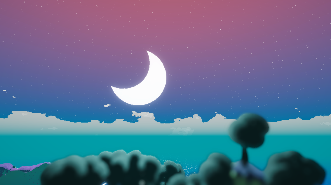
You might not need one! But it is really fun to work on one. My currently untitled game (EDIT: it’s called Shutter Stroll and is out already!) is an exploration game with procedurally generated islands. So whenever you would visit another island, I wanted the place to feel different in every way, so I opted for a custom skybox shader, which can be adjusted in many ways to evoke different atmospheres. Overcast with a dark sky? A big, pale moon among thousands of twinkling stars? A clear day with only a few clouds and the sun up high? Suddenly I can generate skies in addition to my islands, and it improves the game by a lot. I have been posting development over on Twitter, and reception has been great!
I want to break down the general structure of my shader, so you can build your own skyboxes on top of it! Keep in mind that this is not exactly the shader I am using since I like to tweak it a lot, but the features are the same, and you will be able to easily extend it. Let’s jump into it!
Colouring the sky 🌈
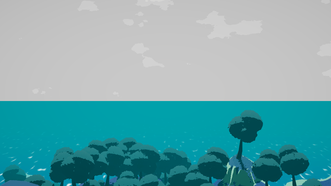
Okay, let’s begin with the thing that will cover the area on our skybox: the sky. Sure, you could just pick a color and be done with it, but it might look a bit bland. Look at the picture on the left: the sky is not colored uniformly, there is a gradient originating from the horizon upwards. I won’t go into scientific details here, because we do not aim to be particularly realistic, it just so happens that nature is really pretty in this regard! So let’s pick two colors, and interpolate them based on height. So…how do I determine the height?!
Unwrapping the skybox
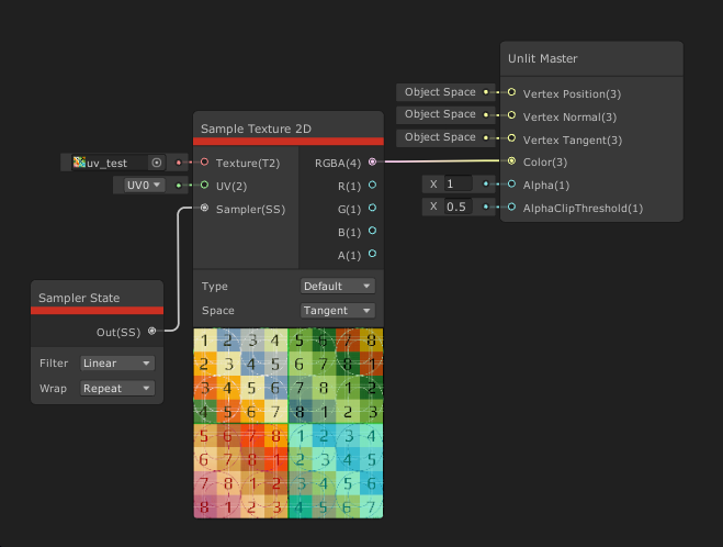
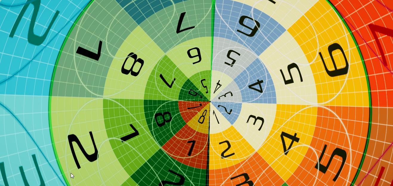
To properly judge whether our calculated coordinates are right, I used a UV test texture by Thomas Schall for the visualization. You can find the texture over here.
So let’s just plug a Sample Texture 2D node into the Color input of our master node and see what happens!
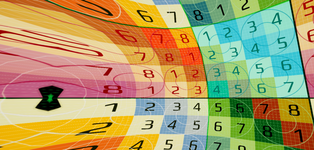
It’s clear to see that our UV coordinates are all over the place! It might not matter too much for the vertical gradient (still stretched near the top!) but it will matter on the horizontal axis! So let us fix that!
We will be doing the following things:
- Get the World Position and Normalize it. That way we can make sure we are working on a sphere, which is the shape we’d like our skybox to have.
- Take the Arcsine of the Y component. This will eliminate the stretch near the top. We still need to divide the value by Pi/2, since Arcsin(1) = Pi/2.
- Calculate the Arctangent2 of the X and Z component. This will return the angle on the circumference of our skybox. Divide it by Tau (You can use the Constant node to get the value of Tau).
Tau is Pi times 2. Most of the time, you will double Pi anyway, so just use Tau. Tau is the cooler Pi.
4. Lastly, recombine the (now two) components into one Vector2. These are our UV coordinates!
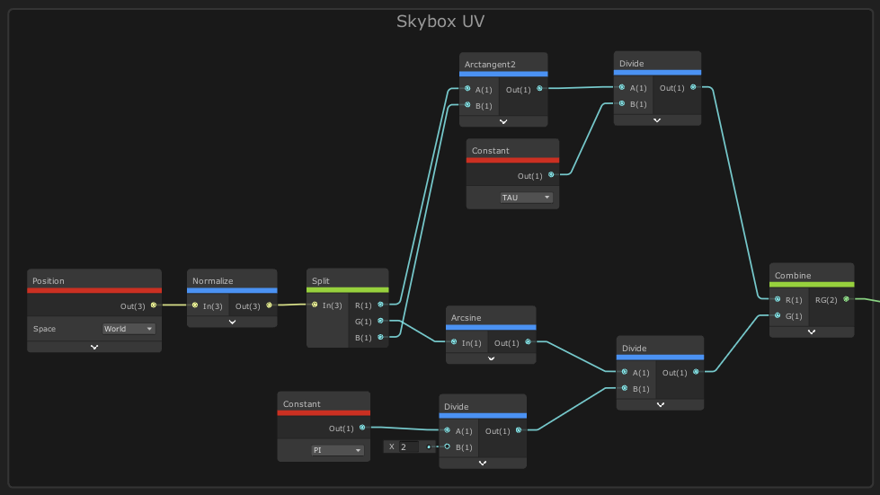
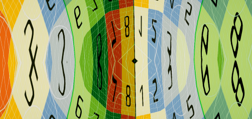
We can convert this into a subgraph, so we don’t have to look at this anymore! Plug it into the UV input on the Sample Texture 2D node and you should see the following:
Now let us finally put some colors into this thing! I’ll create two properties and call them HorizonColor and SkyColor. Then we will interpolate between them with a Lerp node, based on the V component of our new UV node.
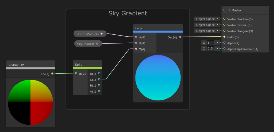
Pro Tip: Instead of interpolating the color values in RGB space, you can lerp in HSV space instead! Interpolating the Hue, Saturation and Value components separately can lead to prettier results! But this breakdown is already long as is, so I will be skipping over that.
You can play around with the colors to find a combination you like. There is one small problem though: without other objects in the scene, it is hard to judge in which direction you are looking currently. Let’s change that by adding stars! ✨
Adding sparkles: Stars ✨

The base for our starfield will be the Voronoi node. Voronoi patterns are really handy for a variety of shaders! This pattern is constructed by placing semi-randomly distributed points, and then every pixel gets a value depending on its distance to the nearest point. This does not look like stars at all yet, but we can take advantage of the generated points to draw stars! So here’s what we will do:
- We’ll Saturate the output of the Voronoi node. Since some pixels have a distance greater than 1 to some of the points, this would leave us with some artifacts on our sky. (the Saturate node clamps values between 0 and 1)
- Using the One Minus node we invert the values, leaving us with something that looks like bubbles.
- Now we could step the result by some high value (0.95-.99), and that would leave us with nice circles. But I will use a Power node with a high power value (~100) instead because I think it looks nicer!
- Lastly, we plug our Skybox UV into a Tiling and Offset node, set the tiling to [8,2] (to correct the horizontal stretch and get a smaller scale) and route that into the UV input of the Voronoi.
- Add the result onto our gradient sky and plug the result into the Color of the master node.
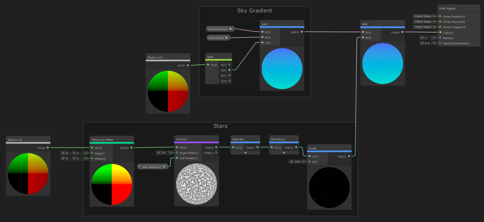
Notice I created a property to control the star density, which I’ve set at 10 for now. I also increased the Voronoi angle offset, otherwise our stars will look like we placed them on a grid.
Now might be a good time to create a material, assign the shader and set it as our skybox material.
You can change the current skybox material under Window > Rendering > Lighting Settings. It’s right up top. This is scene-specific; so you will need to assign it in every scene you need the skybox. You will see a warning that the material does not support skybox rendering, but it will work just fine!

The big pale moon (or sun?) 🌙
Right now we can’t see where the light in our scene is coming from, so let’s add a sun (or moon)! We could set the sun’s position in the sky by hand, but I would like to have it follow our main directional light! The fastest way is to add a script to your light with the following line of code in its Start() function (or Update(), if you move your light during gameplay):
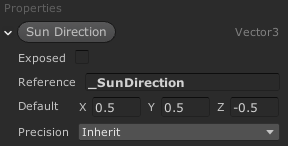
Shader.SetGlobalVector(“_SunDirection”, transform.forward);Now we can access the light direction in our shader! We just need to create a Vector3 property, set its reference to “_SunDirection” and untick the Exposed checkbox. This tells our property that we don’t want to set it by hand in the material inspector later, but that it should read global shader variables, like the one we just set in our script.
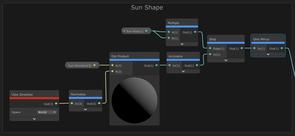
We will be using the dot product of our sun direction and the view direction of each fragment to see if the directions align. The View Direction is a vector spanning from the position of the fragment directly to the camera! The Dot Product node will return 1 if the vectors align and -1 when they are exact opposites. If they are perfectly perpendicular, we will see a value of 0. In other words: a value of 1 means we are staring directly into the sun, so we’ll put on sunglasses and do the following things:
- We’ll Normalize the output of a View Direction node (set to world space). Since the view direction points from the fragment position to the camera, it’s a pretty long vector! Save yourself some trouble by normalizing it right at the start.
- Calculate the Dot Product of the light direction and the normalized view direction!
- (Optional, but recommended) We can run the result through the Arcosine node to change the rate the value changes over the surface of our sphere. This will help us change our sun size later.
- Step the result with a value between 0 and 1. We can expose this as a property that we will call Sun Size.
- Invert the value range by running it through the One Minus node.

Let us add this effect on top of the sky and the stars, and see how it looks! You might need to tweak the sun size first, I recommend starting at a value of ~0.1, which is still pretty big for most cases. Our sun has a pretty sharp edge though, how can we change that? In most cases, I would swap the Step node with a Smoothstep one. In this case, I will use bloom in my post-processing, so that will soften the edge instead.
Pro tip: Since most of the desired values for the sun size are near 0, I like to multiply the sun size by itself, to get a tiny bit more granularity in those lower values.

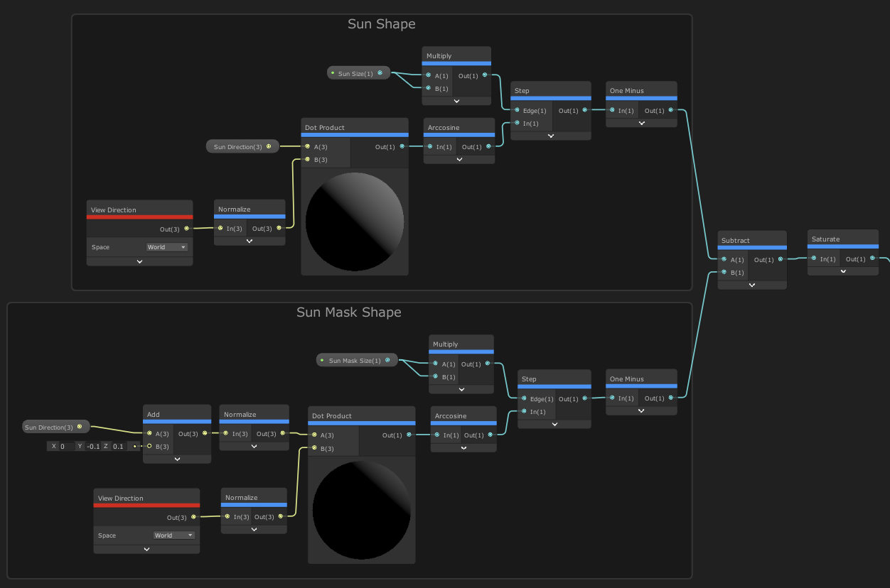
Now, we could stop here. But we are already able to draw one circle, so maybe we can draw another one and subtract it from the first one in order to get a nice moon shape?
This is actually pretty easy! We will duplicate the node setup we just built, but this time we will add a small offset to the light direction. That way the center of our second sun is shifted slightly. Then we subtract the result from our first sun, saturate that value and we are done with our moon shape! We could even split the two sun sizes into their own properties, so we can tweak them independently.
Let us take a look at the final graph for the moon:
Clouds ☁
Right now our horizon is a bit empty, and I would like to see some clouds back there, so let us try making some!

We will be using a seamless noise texture for the clouds, just like the one on the left. You can use your own texture, just make sure that it is tileable! The type of texture you choose will drastically change the look of the clouds, so experiment with them to find a look you like.
The graph for the clouds will be a bit larger since we need to adjust values at every corner, so I will show you the first part of the graph beforehand; that might make it easier to follow along! You can expose many of the values used here as properties, but I don’t want to have a ton of properties in my inspector that I will rarely use. With that said, let’s get into it!
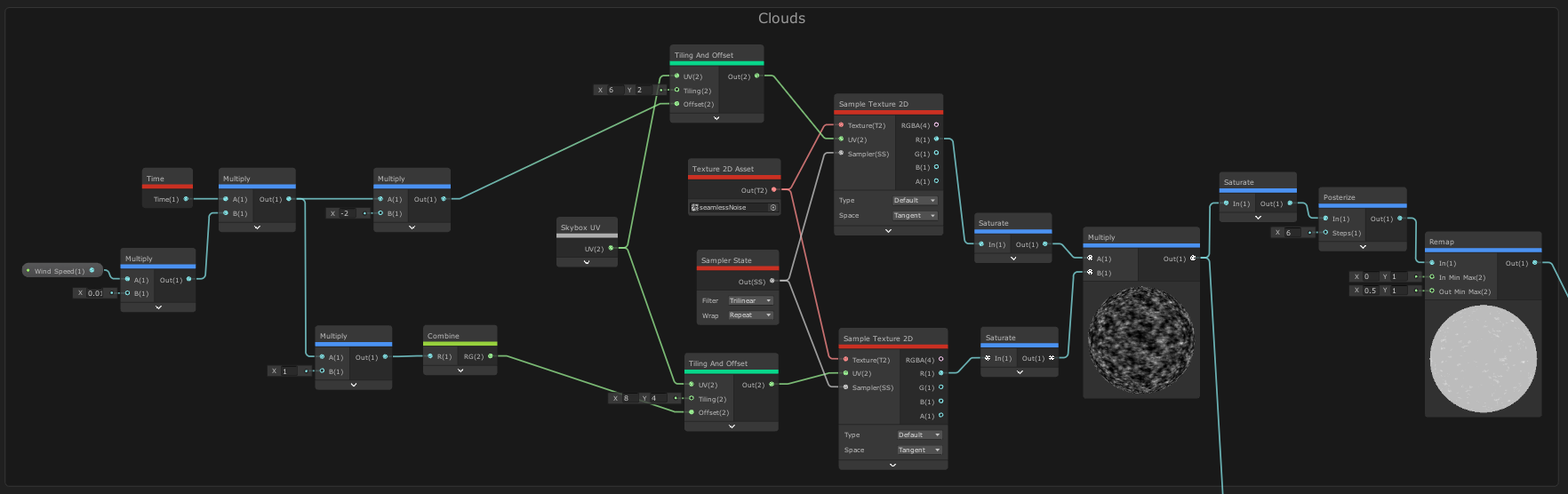
Let’s walk through this step by step:
- We’ll create a float property called Wind Speed. We will multiply this by the linear time value of the Time node to calculate the speed the clouds will move at. (I multiply it by 0.01 before that, so I have more control in the inspector)
- We feed the resulting speed into the offset input of a Tiling and Offset node, which also receives our Skybox UV. This will move our UV over time. I also turn up the tiling, to make the texture repeat over the whole sphere (use integer values here)
- We use a Sample Texture 2D node to with our new UV and our texture as an input to get access to the color values in the texture. We will use the Red channel output moving forward since a greyscale image should have equal values across all channels. Otherwise, we would need to work with a Vector4 here, which just complicates things.
- We Saturate the result just in case, then we copy what we have done and repeat it a second time below, this time changing the offset (use the opposite sign so the two textures scale in opposite directions) and using higher tiling values.
- Now we can multiply both values, Saturate them again (probably unnecessary, but I like to be safe), and Posterize it to stylize it a bit.
- At the end we Remap the result because we don’t need the values between 0 and 0.5, they are simply too dark for clouds!
I’ll plug the result straight into our Color input of the Master node, this is how it looks:
Of course, you can multiply the result with any color you’d like, but for simplicity’s sake, I’ll be skipping over that for now. We still need to mask our cloud effect, and it would be great if we could control how high the clouds appear along the horizon!
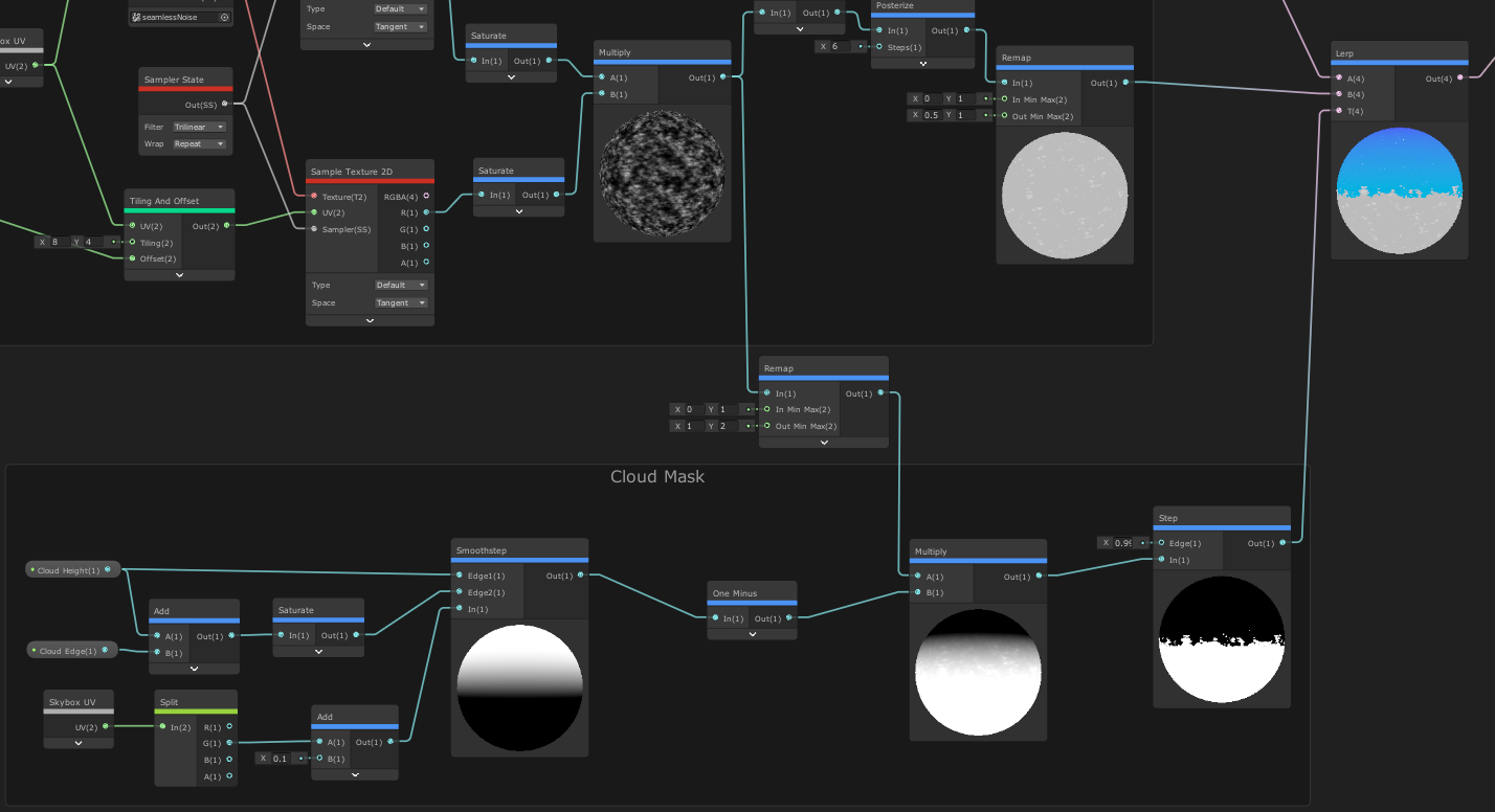
- Let us isolate the V component of our Skybox UV and feed it into a Smoothstep node. The lower Edge will be where we want our clouds to start (between 0 and 1), and we add another value on top of that for the second edge. That way we can control how far the clouds should fade out.
- We invert the value range with the One Minus node (so 1 is near the horizon, and 0 high up in the sky) and multiply it with our combined cloud texture. I will remap the cloud values to go from 1 to 2 so that it won’t erase completely white parts of the gradient.
- We step the result again at a high value to get a clean edge, and now our mask is done!
- To put it into effect, we can create a Lerp node, assign our mask to the T value and plug in our existing sky color and our clouds! Route the result into our master node yet again and we should see something like this:
We could stop here, as we are already at it for quite some time now, but I don’t like the harsh intersection between the sky and the ocean below it. You might notice that We do have fog in our scene, but under normal circumstances, skyboxes don’t get affected by fog! So let us try to blend that edge, and we will be done!
Hiding the horizon: Fog! 🌫
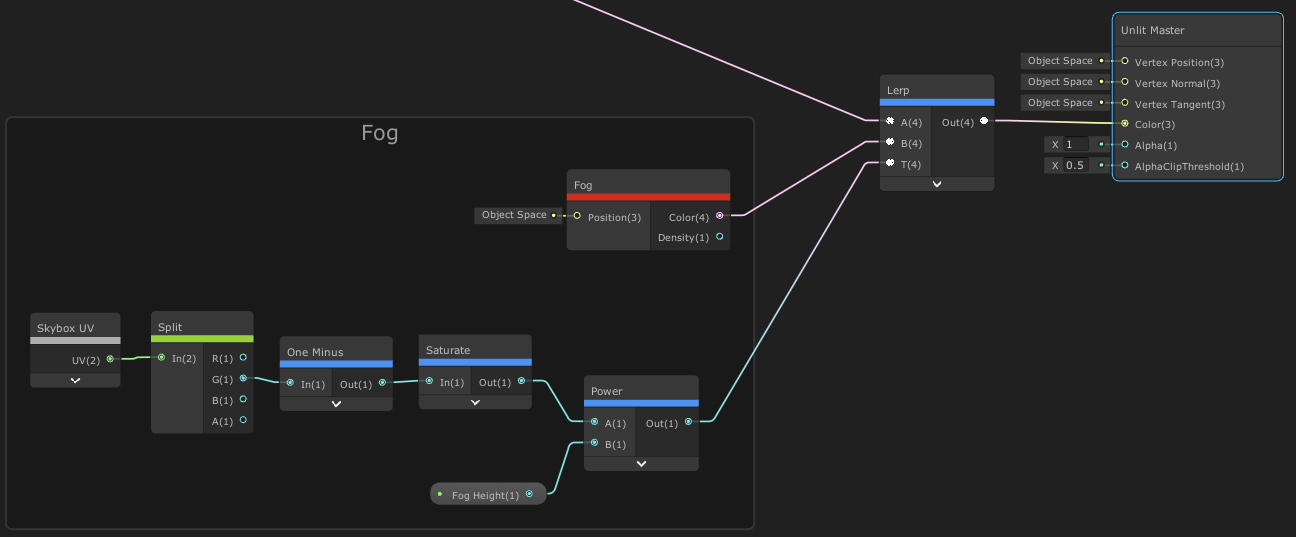
- Let’s isolate the V component of the Skybox UV again, invert the value range as we have done multiple times already and saturate the result.
- Use the Power node to change the value ramp, I think a power value of 25 is a good start, but we can expose it as a property because this might change often.
- Lastly, use the Fog node to get the scene fog color, and lerp it using our value. And with that, we are done!
And with this, we are done! You can take a look at the finished graph, it is not that big!

You can explore the graph in its full glory over here! You’ll also be able to download it there, but I can only recommend building it yourself and experimenting every step of the way!
Thank you for reading my shader breakdown! I hope this serves as a good inspiration for creating your own sky shaders. If you end up doing something with it, I would love to see it! Just mention me on Twitter, where I am most active!
If you’d like to play Shutter Stroll, the game that I created a more complex version of this shader for, you can wishlist the game on Steam!